Sabado, Agosto 23, 2014

Superposition Theorem

The strategy used in the Superposition Theorem is to eliminate all but one source of power within a network at a time, using series/parallel analysis to determine voltage drops (currents) within the modified network for each power source separately. Let's look at our example circuit again and apply Superposition Theorem to it:
Since we have two sources of power in this circuit, we will have to calculate two sets of values for voltage drops and/or currents, one for the circuit with only the 28 volt battery in effect. . .
. . . and one for the circuit with only the 7 volt battery in effect:
When re-drawing the circuit for series/parallel analysis with one source, all other voltage sources are replaced by wires (shorts), and all current sources with open circuits (breaks). Since we only have voltage sources (batteries) in our example circuit, we will replace every inactive source during analysis with a wire.

Source Transformation

Source Transformation of Circuits- Explained

Source transformation
The source transformation of a circuit is the transformation of a power source from a voltage source to a current source, or a current source to a voltage source.
In other words, we transform the power source from either voltage to current, or current to voltage. 

Voltage Source Transformation

We will first go over voltage source transformation, the transformation of a circuit with a voltage source to the equivalent circuit with a current source.
In order to get a visual example of this, let's take the circuit below which has a voltage source as its power source:
Voltage Source Transformation

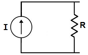
Using source transformation, we can change or transform this above circuit with a voltage power source and a resistor, R, in series, into the equivalent circuit with a current source with a resistor, R, in parallel, as shown below:

Current Source Transformation
We transform a voltage source into a current source by using ohm's law. A voltage source can be changed into a current source by using ohm's formula,I=V/R

Biyernes, Agosto 8, 2014

Mesh Current, conventional method


The first step in the Mesh Current method is to identify “loops” within the circuit encompassing all components. In our example circuit, the loop formed by B1, R1, and R2 will be the first while the loop formed by B2, R2, and R3 will be the second. The strangest part of the Mesh Current method is envisioning circulating currents in each of the loops.


The choice of each current's direction is entirely arbitrary, just as in the Branch Current method, but the resulting equations are easier to solve if the currents are going the same direction through intersecting components (note how currents I1 and I2 are both going “up” through resistor R2, where they “mesh,” or intersect). If the assumed direction of a mesh current is wrong, the answer for that current will have a negative value.
The next step is to label all voltage drop polarities across resistors according to the assumed directions of the mesh currents.

Using Kirchhoff's Voltage Law, we can now step around each of these loops, generating equations representative of the component voltage drops and polarities. As with the Branch Current method, we will denote a resistor's voltage drop as the product of the resistance (in ohms) and its respective mesh current (that quantity being unknown at this point). Where two currents mesh together, we will write that term in the equation with resistor current being the sum of the two meshing currents. 


Wye Delta

Delta to wye conversion
It is easy to work with wye network. If we get delta network, we convert it to wye to work easily. To obtain the equivalent resistance in the wye network from delta network we compare the two networks and we confirm that they are same. Now we will convert figure 3 (a) delta network to figure 2 (a) wye network.
From figure 3 (a) for terminals 1 and 2 we get,
R12 (∆) = Rb || (Ra + Rb)
From figure 2 (a) for terminals 1 and 2 we get,
R12(Y) = R1 + R3
Setting wye and delta equal,
R12(Y) = R12 (∆) we get,

http://www.engineersblogsite.com/wp-content/uploads/2013/04/1.png

Equations (v), (vi) and (vii) are the equivalent resistances for transforming delta to wye conversion. We do not need to memorize these equations. Now we create an extra node shown in figure 4 and follow the conversion rule,
Each resistor in the Y network is the product of the resistors in the two adjacent Del branches, divided by the sum of the three Del resistors.


Wye to delta conversion
For conversion to wye network to delta network adding equations (v), (vi) and (vii) we get,
 R1R2 + R2R3 + R3R1 = RaRbRc(Ra +Rb + Rc)/(Ra + Rb + Rc)2
                                = RaRbRc/(Ra + Rb + Rc) —————— (ix)
Dividing equation (ix) by each of the equations (v), (vi) and (vii) we get,
Ra = R1R2 + R2R3 + R3R1/ R1
Rb = R1R2 + R2R3 + R3R1/ R2
Rc = R1R2 + R2R3 + R3R1/ R3
For Y to delta conversion the rule is followed below,

Each resistor in the delta network is the sum of all possible products of Y resistors taken two at a time, divided by the opposite Y resistor.

see link http://waleedeid.tripod.com/Lecture3_cir_analysis.pdf
for more information... :)