Miyerkules, Marso 18, 2015

Complex Power

  1. Complex power is the product of the complex effective voltage and thecomplex effective conjugate current. In our notation here, the conjugate is indicated by an asterisk (*).Complex power can also be computed using the peak values of the complex voltage and current, but then the result must be divided by 2.
Complex Power

In power system analysis the concept of Complex Power is frequently used to calculate the real and reactive power.

This is a very simple and important representation of real and reactive power when voltage and currentphasors are known. Complex Power is defined as the product of Voltage phasor and conjugate of current phasor. See Fig-A

Let voltage across a load is represented by phasor V  and  current through the load is I.

If S is the complex power then,

                 S = V . I*

V is the phasor representation of voltage and I* is the conjugate of current phasor. 

So if  V is the reference phasor then V can be written as |V| ∠0.
(Usually one phasor is taken reference which makes zero degrees with real axis. It eliminates the necessity of introducing a non zero phase angle for voltage)

Let current lags voltage by an angle φ, so  I = | I | ∠-φ
(current phasor makes -φ degrees with real axis)

                            I*=  | I | ∠φ
So,
                           S = |V|  | I | ∠(0+φ) =  |V|  | I | ∠φ

(For multiplication of phasors we have considered polar form to facilitate calculation)

Writting the above formula for S in rectangular form we get

                           S =  |V|  | I | cos φ  +  j  |V|  | I | sin φ 
             The real part of complex power S is |V| | I | cos φ which is the real power or average power and the imaginary part  |V| | I | sin φ is the reactive power. 

             So,              S = P + j Q


             Where        P = |V| | I | cos φ    and    Q = |V| | I | sin φ

It should be noted that S is considered here as a complex number. The real part P is average power which is the average value, where as imaginary part is reactive power which is a maximum value. So I do not want to discuss further and call S as phasor. If you like more trouble I also advise you to read my article about phasor or some other articles on phasor and complex numbers.


The apparent power is the vector sum of real and reactive power
Engineers use the following terms to describe energy flow in a system (and assign each of them a different unit to differentiate between them):
  • Real power (P) [Unit: W]
  • Reactive power (Q) [Unit: VAR]
  • Complex power (S)
  • Apparent Power (|S|) [Unit: VA]: i.e. the absolute value of complex power S.

Power Factor

Power Factor

In AC circuits, the power factor is the ratio of the real power that is used to do work and theapparent power that is supplied to the circuit.
The power factor can get values in the range from 0 to 1.
When all the power is reactive power with no real power (usually inductive load) - the power factor is 0.
When all the power is real power with no reactive power (resistive load) - the power factor is 1.

Power factor definition

The power factor is equal to the real or true power P in watts (W) divided by the apparent power |S| in volt-ampere (VA):
PF = P(W) / |S(VA)|
PF - power factor.
P   - real power in watts (W).
|S|   - apparent power - the magnitude of the complex power in volt·amps (VA).

Power factor calculations

For sinusuidal current, the power factor PF is equal to the absolute value of the cosine of the apparent power phase angle φ (which is also is impedance phase angle):
PF = |cos φ|
PF is the power factor.
φ   is the apprent power phase angle.

The real power P in watts (W) is equal to the apparent power |S| in volt-ampere (VA) times the power factor PF:
P(W) = |S(VA)| × PF = |S(VA)| × |cos φ|

When the circuit has a resistive impedance load, the real power P is equal to the apparent power |S| and the power factor PF is equal to 1:
PF(resistive load) = P / |S| = 1

The reactive power Q in volt-amps reactive (VAR) is equal to the apparent power |S| in volt-ampere (VA) times the sine of the phase angle φ:
Q(VAR) = |S(VA)| × |sin φ|
Single phase circuit calculation from real power meter reading P in kilowatts (kW), voltage V in volts (V) and current I in amps (A):
PF = |cos φ| = 1000 × P(kW) / (V(V) × I(A))

Three phase circuit calculation from real power meter reading P in kilowatts (kW), line to line voltageVL-L in volts (V) and current I in amps (A):
PF = |cos φ| = 1000 × P(kW) / (3 × VL-L(V) × I(A))

Three phase circuit calculation from real power meter reading P in kilowatts (kW), line to line neutralVL-N in volts (V) and current I in amps (A):
PF = |cos φ| = 1000 × P(kW) / (3 × VL-N(V) × I(A))

Power factor correction

Power factor correction is an adjustment of the electrical circuit in order to change the power factor near 1.
Power factor near 1 will reduce the reactive power in the circuit and most of the power in the circuit will be real power. This will also reduce power lines losses.
The power factor correction is usually done by adding capacitors to the load circuit, when the circuit has inductive components, like an electric motor.

Power factor correction calculation

The apparent power |S| in volt-amps (VA) is equal to the voltage V in volts (V) times the current I in amps (A):
|S(VA)| = V(V) × I(A)
The reactive power Q in volt-amps reactive (VAR) is equal to the square root of the square of the apparent power |S| in volt-ampere (VA) minus the square of the real power P in watts (W) (pythagorean theorem):
Q(VAR) = √(|S(VA)|2 - P(W)2)
The reactive power Q in volt-amps reactive (VAR) is equal to the square of voltage V in volts (V) divided by the reactance Xc:
Q(VAR) = V(V)2 / XC = V(V)2 / (1 / (2πf(Hz)·C(F))) = 2πf(Hz)·C(F)·V(V)2
So the power factor correction capacitor in Farad (F) that should be added to the circuit in parallel is equal to the reactive power Q in volt-amps reactive (VAR) divided by 2π times the frequency f in Hertz (Hz) times the squared voltage V in volts (V):
C(F) = Q(VAR) / (2πf(Hz)·V(V)2)

Apparent Power Value

  1. The combination of reactive power and true power is called apparent power, and it is the product of a circuit's voltage and current, without reference to phase angle. Apparent power is measured in the unit of Volt-Amps (VA) and is symbolized by the capital letter S.
  2. Apparent power is a measure of alternating current (AC) power that is computed by multiplying the root-mean-square (rms) current by the root-mean-square voltage. In a direct current (DC) circuit, or in an AC circuit whose impedance is a pure resistance, the voltage and current are in phase, and the following formula holds:
  3. P = ErmsIrms
    where P is the power in watts, Erms is the root-mean-square (rms) voltage in volts, and Irmsis the rms current in amperes. But in an AC circuit whose impedance consists of reactance as well as resistance, the voltage and current are not in phase. This complicates the determination of power.
    In an AC circuit, the product of the rms voltage and the rms current is called apparent power. When the impedance is a pure resistance, the apparent power is the same as thetrue power. But when reactance exists, the apparent power is greater than the true power. The vector difference between the apparent and true power is called reactive power.
    If Pa represents the apparent power in a complex AC circuit, Pt represents the true power, and Pr represents the reactive power, then the following equation holds:
    Pa2 = Pt2 + Pr2

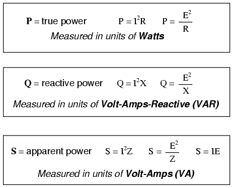
There are several power equations relating the three types of power to resistance, reactance, and impedance (all using scalar quantities):
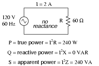
Please note that there are two equations each for the calculation of true and reactive power. There are three equations available for the calculation of apparent power, P=IE being useful only for that purpose. Examine the following circuits and see how these three types of power interrelate for: a purely resistive load in Figure below, a purely reactive load in Figure below, and a resistive/reactive load in Figure below.
Resistive load only:
True power, reactive power, and apparent power for a purely resistive load.
Reactive load only:
True power, reactive power, and apparent power for a purely reactive load.
Resistive/reactive load:
True power, reactive power, and apparent power for a resistive/reactive load.
These three types of power -- true, reactive, and apparent -- relate to one another in trigonometric form. We call this the power triangle: (Figure below).
Power triangle relating appearant power to true power and reactive power.


Effective or RMS Value


Maximum Average Power Transfer

Maximum Average Power is transferred from a source to a load, the load impedance should be chosen equal to the conjugate of the Thevenin equivalent impedance representing the reminder of the network.


Maximum power transfer theorem is explained by the figure. Let a network consisting of one or more independent sources and other resistive elements be represented by its Thevenin's equivalent circuit.  We find out now the value of load resistance for which the power transferred to it is the maximum.


The average power dissipated in the load is the square of the current multiplied by the resistive portion (the real part)   of the load impedance.


Instantaneous and Average Power

Instantaneous and Average Power in an AC Circuit

The instantaneous power at any one moment is the same as in a DC circuit - Joules Law
The average power is the time average of the power over one period.
For a current driven circuit we can rewrite this as,


In AC circuit analysis, what is this power that we talk about. The main problem is that the AC voltage and current varies sinusoidally with time. Moreover the presence of circuit reactive elements like Inductor and capacitor shift the current wave with respect to voltage wave (angle of phase difference). 

Power is rate at which energy is consumed by load or produced by generator. Whether it is DC circuit or AC circuit, the value of instantaneous power is obtained by multiplying instantaneous voltage with instantaneous current. If at any instant of time t the voltage and current values are represented by sine functions as

         v = Vm  sin ωt  

          i = Im  sin (ωt-φ)
Vm and Im  are the maximum values of the sinusoidal voltage and current. Here ω=2 π f
f is the frequency and ω is the angular frequency of rotating voltage or current phasors. It should be clear that for a power system f is usually 50 or 60 Hz
φ is the phase difference between the voltage and current.

As we said the instantaneous power is the product of instantaneous voltage and current, if we name instantaneous power as p then

p = v.i =  Vm  sin ωt  .  Im  sin (ωt-φ)
         or  p = Vm Im  sin ωt  sin (ωt-φ)

Applying trigonometric formula 2.sin A.sin B = cos(A-B) - cos (A+B)  we get

It can be written as


Lunes, Pebrero 23, 2015

Thevenin's Theorem in AC Analysis


Source Transformation in AC Analysis


  • Transform a voltage source in series with an impedance to a current source in     parallel with an impedance for simplification or vice versa.


Source transformations are easy to perform as long as there is a familiarity with Ohm's law. If there is a voltage source in series with an impedance, it is possible to find the value of the equivalent current source in parallel with the impedance by dividing the value of the voltage source by the value of the impedance. The converse also applies here: if a current source in parallel with an impedance is present, multiplying the value of the current source with the value of the impedance will result in the equivalent voltage source in series with the impedance.

Superposition Theorem in AC Analysis

The superposition theorem states that in a linear circuit with several sources, the current and voltage for any element in the circuit is the sum of the currents and voltages produced by each source acting independently. The theorem is valid for any linear circuit. The best way to use superposition with AC circuits is to calculate the complex effective or peak value of the contribution of each source applied one at a time, and then to add the complex values. This is much easier than using superposition with time functions, where one has to add the individual time functions.
To calculate the contribution of each source independently, all the other sources must be removed and replaced without affecting the final result.
When removing a voltage source, its voltage must be set to zero, which is equivalent to replacing the voltage source with a short circuit.
When removing a current source, its current must be set to zero, which is equivalent to replacing the current source with an open circuit. 
Now let's explore an example. 
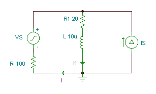
In the circuit shown below" 
Ri = 100 ohm, R1 = 20 ohm, R2 = 12 ohm, L = 10 uH, C = 0.3 nF, vS(t)=50cos(wt) V, iS(t)=1cos(wt+30°) A, f=400 kHz. 
Notice that both sources have the same frequency: we will only work in this chapter with sources all having the same frequency. Otherwise, superposition must be handled differently.
Find the currents i(t) and i1(t) using the superposition theorem.


  • REVIEW:
  • The Superposition Theorem states that a circuit can be analyzed with only one source of power at a time, the corresponding component voltages and currents algebraically added to find out what they'll do with all power sources in effect.
  • To negate all but one power source for analysis, replace any source of voltage (batteries) with a wire; replace any current source with an open (break).

Sabado, Enero 3, 2015

AC Circuits:Nodal Analysis & Mesh Analysis


Ø Since KCL is valid for phasors, we can analyze AC circuits by NODAL analysis.
Ø Determine the number of nodes within the network.
Ø Pick a reference node and label each remaining node with a subscripted value of voltage: V1, V2 and so on.
Ø Apply Kirchhoff’s current law at each node except the reference. Assume that all unknown currents leave the node for each application of Kirhhoff’s current law.
Ø Solve the resulting equations for the nodal voltages.
Ø For dependent current sources: Treat each dependent current source like an independent source when Kirchhoff’s current law is applied to each defined node. However, once the equations are established, substitute the equation for the controlling quantity to ensure that the unknowns are limited solely to the chosen nodal voltages.


ØPractice Problem 10.1: Find v1 and v2 using nodal analysis


Mesh Analysis

Practice Problem 10.4: Calculate the current Io

Impedance and Admittance

Susceptance and Admittance

Admittance (symbolized Y ) is an expression of the ease with which alternating current ( AC ) flows through a complex circuit or system. Admittance is a vector quantity comprised of two independent scalar phenomena: conductance and susceptance .

Impedance, denoted Z, is an expression of the opposition that an electronic component, circuit, or system offers to alternating and/or direct electric current.Impedance is a vector (two-dimensional)quantity consisting of two independent scalar (one-dimensional) phenomena: resistance and reactance.


In the study of DC circuits, the student of electricity comes across a term meaning the opposite of resistance: conductance. It is a useful term when exploring the mathematical formula for parallel resistances: Rparallel = 1 / (1/R1 + 1/R2 + . . . 1/Rn). Unlike resistance, which diminishes as more parallel components are included in the circuit, conductance simply adds. Mathematically, conductance is the reciprocal of resistance, and each 1/R term in the “parallel resistance formula” is actually a conductance.
Whereas the term “resistance” denotes the amount of opposition to flowing electrons in a circuit, “conductance” represents the ease of which electrons may flow. Resistance is the measure of how much a circuit resists current, while conductance is the measure of how much a circuit conducts current. Conductance used to be measured in the unit of mhos, or “ohms” spelled backward. Now, the proper unit of measurement is Siemens. When symbolized in a mathematical formula, the proper letter to use for conductance is “G”.
Reactive components such as inductors and capacitors oppose the flow of electrons with respect to time, rather than with a constant, unchanging friction as resistors do. We call this time-based opposition, reactance, and like resistance we also measure it in the unit of ohms.
As conductance is the complement of resistance, there is also a complementary expression of reactance, called susceptance. Mathematically, it is equal to 1/X, the reciprocal of reactance. Like conductance, it used to be measured in the unit of mhos, but now is measured in Siemens. Its mathematical symbol is “B”, unfortunately the same symbol used to represent magnetic flux density.
The terms “reactance” and “susceptance” have a certain linguistic logic to them, just like resistance and conductance. While reactance is the measure of how much a circuit reacts against change in current over time, susceptance is the measure of how much a circuit is susceptible to conducting a changing current

Series-parallel R, L, and C

Now that we've seen how series and parallel AC circuit analysis is not fundamentally different than DC circuit analysis, it should come as no surprise that series-parallel analysis would be the same as well, just using complex numbers instead of scalar to represent voltage, current, and impedance.
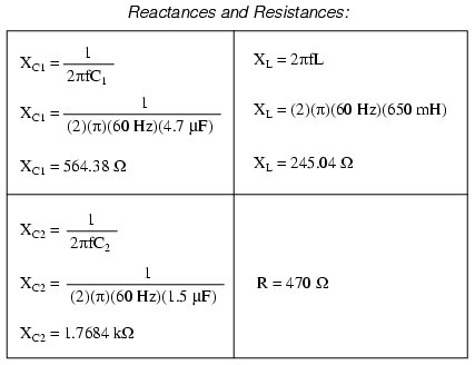
Take this series-parallel circuit for example: (Figure below)


Sinusoids and Phasors

A Sinusoid is a signal that has the form of the sine or cosine function.


A sinusoidal current is usually referred to as alternating current (ac).
Such a current reverses at regular time intervals and has alternately pos-
itive and negative values. Circuits driven by sinusoidal current or volt-
age sources are called ac circuits.


A sinusoidal forcing function produces both a transient response
and a steady-state response, much like the step function, which we stud-
ied in Chapters 7 and 8. The transient response dies out with time so
that only the steady-state response remains. When the transient response
has become negligibly small compared with the steady-state response,
we say that the circuit is operating at sinusoidal steady state. It is this
sinusoidal steady-state response.


A sinusoid having period T and angular frequency can be represented as


A periodic function is one that satisfies f (t) f (tnT), for all t and
for all integers n.


Basically a rotating vector, simply called a “Phasor” is a scaled line whose length represents an AC quantity that has both magnitude (“peak amplitude”) and direction (“phase”) which is “frozen” at some point in time.

A phasor is a vector that has an arrow head at one end which signifies partly the maximum value of the vector quantity ( V or I ) and partly the end of the vector that rotates.

  • Polar representation:$z = \vert z\vert\;e^{j\angle z}$, or simply $z=\vert z\vert\;\angle z$, where $\vert z\vert$ and $\angle z$ are the magnitude and phase angle, respectively.
complex_number.gif
The two representations can be converted from one to the other:
  • From $(x,y)$ to $(\vert z\vert,\angle z)$:

    \begin{displaymath}\left\{ \begin{array}{ll} \vert z\vert=\sqrt{x^2+y^2} & \mbox...
...gle z=tan^{-1} (y/x) & \mbox{phase angle}
\end{array} \right. \end{displaymath}

  • From $(\vert z\vert,\angle z)$ to $(x,y)$:

    \begin{displaymath}z=\vert z\vert\;e^{j\angle z}=\vert z\vert(\cos\angle z+j\;\sin\angle z)=x+jy \end{displaymath}


    due to Euler identity, i.e.,

    \begin{displaymath}\left\{ \begin{array}{ll} x=\vert z\vert\;\cos\angle z & \mbo...
...ert\;\sin\angle z & \mbox{imaginary part}
\end{array} \right. \end{displaymath}

The arithmetic operations of two complex numbers $z=x+jy=\vert z\vert\;e^{j\angle z}$ and $w=u+jv=\vert w\vert\;e^{j\psi}$ are listed below:
  • Add/Subtract:

    \begin{displaymath}z+w=(x+u)+j(y+v),\;\;\;\;z-w=(x-u)+j(y-v) \end{displaymath}


  • Multiply:

    \begin{displaymath}z\;w=(x+jy)(u+jv)=(xu-yv)+j(xv+yu)=\vert z\vert\;\vert w\vert\;e^{j(\angle z+\angle w)} \end{displaymath}


  • Divide:

    \begin{displaymath}\frac{z}{w}=\frac{x+jy}{u+jv}=\frac{(x+jy)(u-jv)}{(u+jv)(u-jv...
...
=\frac{\vert z\vert}{\vert w\vert}\;e^{j(\angle z-\angle w)} \end{displaymath}